
| Home | |
| Who Are We? | |
| What are we Looking for? | |
| How we do it? | |
| Technical Data | |
| Boonah Space Centre | |
| Solar Power Station | |
| What's New | |
| News Flash | |
| Join Us | |
| Fund Raising | |
| Advisory Board | |
| Our Observatories | |
| Download | |
| Links | |
| Bruno Award | |
| Can SETI Succeed | |
| Space Communication | |
| Contact Us | |
| SETI League | |
| Australian Women Scientists | |
| Australian Astronomers | |
| Aust. Astrobiology Institute | |
| Brisbane Planetarium | |
| S.E.T.I@Home | |
| S.E.T.I Australia | |
| Sky & Telescope Seti Site | |
| Invitation to ET | |
| 3D Universe | |
| COSETI website | |
| Universe Today | |
| Space Daily | |
| Space.com | |
| Spaceref.com | |
| Hubble News | |
| Space Flight Now | |
| SpaceToday.net | |
| Liquid Water on Mars? | |
| Science News Online | |
| Physics | |
| Another look at "WOW" | |
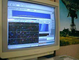
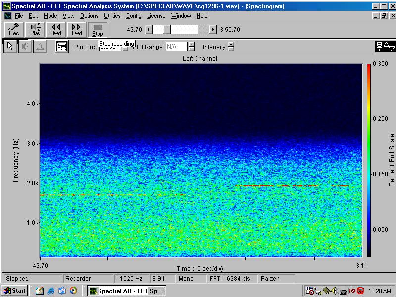
| **New** We have recently recorded several files from our new 5 metre radio telescope that came into service during the month of October 2003. The first is an updated observation at 1420mhz, the second is the SUN at 1420mhz and the 3rd is a signal received at 1296mhz. The last one is interesting if you want to do a DSP on it as it has some interesting characteristics. You can even analyze them if you want. The files are here 1420.wav Sun1420.wav and 1296.wav. During the recent E.M.E. amateur radio contest on the 15th ~ 16th November 03 we were able to record some signals whilst pointing our dish at the moon. This is the file we recorded cq1296.wav and a spectrogram of the event is here. Some of these files are large at 3mb others at 1.4mb. Also, download Your Own Audio Analysis Program here. | |
|
|
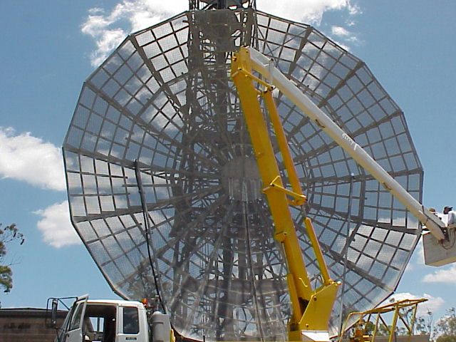
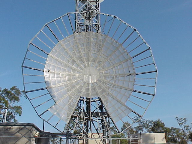
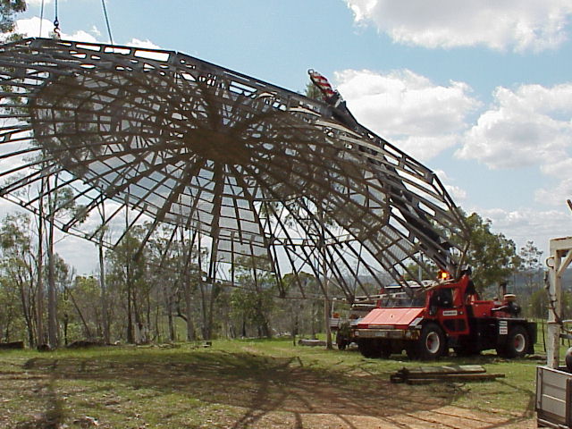
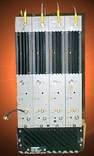
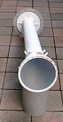
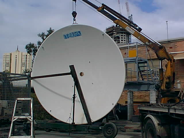
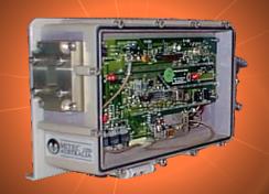
Technical Data Preliminary Technical Data for Microwave Observatory We plan to have two Project Argus systems running 24 hours a day at the site and we have started the construction the new receiving systems that will be use for the two large 14metre dishes. These are based on the Lenkurt microwave systems donated by Power-link. Operating on the L- Band we expect to be able to stretch these systems to operate up to 1670mhz with a few modifications. The Hydrogen line feed horns we will use, have been supplied originally by Andrews Antennas and are perfectly matched to the receivers using low loss, two inch hard line coax cable. The high quality of these instruments will ensure that we get the maximum amount of signal to the receivers. The 5metre dish supplied by Telstra will be connected to an 11 ~ 12Ghtz receiver / down-converter that we will use to do some work in the Ku band. This band is typically used for satellite up-link and downlink but there are a few spots that are quiet enough for us to have a peek to see what's up there. Once we get this dish up we will do some testing to see how bad this band is for noise. The existing Argus system located in Kenmore, Brisbane will be shut down and the hardware moved to the Boonah site to be used for another project. The picture sequence below show how our 14mtre dishes came down from their previous locations. At left still on the tower and intact. Second from left much of the surface and tripod removed and ready for the lift. Third from left in mid air after being lifted off the tower. At right just before touch down on the ground. . Our ear to the universe for these systems will be Antenna's that were obtained from Queensland's Power-link, distributors of electricity in Queensland and the Telecom Company TELSTRA. The 5mtr antenna donated to us from Telstra will allow us to probe the universe at 11 ~ 12 gigahertz. The telescopes will also be made available for use by interested schools and colleges. A 7Metre antenna from the old Fluer's Chris-Cross radio observatory was moved to Brisbane a year ago for restoration purposes This unit was dismantled and moved to Brisbane with the help of Leon Darcy and Alex Hamill. This feat of engineering was accomplished during a particularly hot summer spell. Several companies have helped us with the restoration work of the dishes now onsite at Boonah. MCK Metals provided all the replacement aluminum and E.M.R Switchboards have provided most of the electrical control components. The site will be powered from switchboards manufactured by E.M.R. York Optical Company has been of invaluable service to our Optical Team by way of providing old parts that we can use to make the special fittings we will need for the Optical Observatory We will operate the dishes independently of each other performing a dual targeted search of solar type stars within a shell of 100 light years at frequencies between 1410 MHz and 1675 MHz. At the dish focal point will be a room temperature, low noise amplifier mounted on the feed horn. The feed horn will have two probes mounted inside for dual polarization operation. The choke ring assembly will be optimized to allow dual frequency operation. This will allow switching frequencies between 1420 and 1675mhz. The signals will be fed down to the receivers where they will be applied to the Digital Signal Processing computers and scanned for low level, narrow band signals. Tunable cavity filters will be used to eliminate most of the unwanted signals from adjacent bands that may interfere with our analysis work. The receivers will be a modified version of the Lenkurt (GTE) 82966 microwave system donated by Power-link. The picture below (left) of a Cavity Filter similar to the ones we will use on the hydrogen line L- Band receivers also shown below at second left. The 11Ghz waveguide is shown below second from right and the 5Metre dish far right.
The signal from the first and second stage amplifiers is fed into the receiver bank that is pre-tuned to produce outputs that represent 1420 ~ 1430MHz and 1665 ~ 1675 MHz. We have selected these frequencies to scan as they will give us a range that would represent both red and blue Doppler shifted signals on the Hydrogen and Hydroxyl lines. An alignment signal will also be present at the bottom end of each band that we will use to calibrate our systems with. The output from each receiver is at 35 MHz, the 5 MHz bandwidth, is passed to one of four (4) product detectors that are set to give us a 5 MHZ wide pass band output that is fed directly into the A/D converter (DSP). The 5 MHz signal is then analyzed by the software looking for heterodynes that may signal the detection of a signal. We have installed Cad Technologies P4-1500 computer systems with 512MB Ram, 32mb Matrox Millennium A.G.P. graphics accelerator card, PCI SCSI controller, 9.1gb SCSI Hard disk Drive and a high speed A/D converter for each receiver bank, of which there is 4. Each system is running Windows 98 and a number of software packages to help with the analysis of the data. Antenna position information is obtained from a Planetarium / Astronomy program called The Earth Centered Universe (ECU). This program provides accurate pointing data from the antenna mounted encoders and tells us where the antennas are pointing at any time of the day or night. The screen display updates every minute to show the current position of the antenna. The computer automatically goes into save mode and records the data from the receivers in RAW mode for replay and further analysis. A later enhancement will allow the software to dial a phone number to alert some one that a hit has been received. When a hit occurs, the signal is recorded by videotape as well.
Fast Fourier Transform algorithms are employed to sift through the static looking for similarities in the noise. The 5Mhz band width from our I/F Stage (at 30 ~ 35Mhz) is fed into the Digital Signal Processor and the whole 5Mhz is analyzed down to a resolution of 0.7Htz . This means that we could conceivably detect a narrow bandwidth signal that is only 0.5htz wide providing it is strong enough to trip the software looking at the 0.7Htz bin. We believe that a signal being sent by another civilization, perhaps, as a beacon, would be of a narrow band nature so that it could be detectable and easily noticeable from the background noise. Narrow band signals are not likely to be created by naturally occurring processes and as such, would have a high probability of being artificially manufactured. Our Project Argus Stations are capable of detecting a signal out to about 100 light years depending upon the nature of the transmitting antenna and transmitter power. Civilizations further away from us will be more difficult to detect, as the signals being transmitted would need to be extremely powerful and highly directional for us to detect them. It is probable that the signal will include some sort of information for us to decode and if the sender was interested in us detecting the transmission we expect that it would be rich in information. The other problem is to do with the round trip time. A signal emanating from within a radius of 25 light years could conceivably be answered and some sort of dialogue established between the two parties. Signals from further out would require a longer round trip time for the messages to travel back and forth. The project leaders and scientists could have died before the first round of messages had been negotiated not to mention the effort to decode an alien's thought processes and formulate the reply. We are still working on the Technical Specification for this project but we can tell you some basic specifications of how it will work. The receiver will be capable of operating between 11 and 12 Gigahertz. The Cassegrain type antenna (5 Metre) is fitted with a
Wave-guide and tuning ring assembly that will allow it to be very selective in frequency and beam width. Two high gain front ends (LNC's) will be mounted at the end of the wave-guide cavity, each at 90 degrees to each other. In other words, we will be able to detect both vertical and horizontally polarized signals, and select the stronger one for analysis. The 11/12 Gigahertz signal is down converted to fall within a pass band between 960 ~ 1460 MHz. The resulting output will be fed into the similar receiving bank that is used for Project Argus and analyzed by the computer in a similar way.
Click here for information on Optical Seti Monitoring & Event Recording System designed by students at Brisbane's Griffith University PDF (New)
|
